Toll Booth Project

We are simulating a toll booth, but first we needed to make a state graph and a transition table to come up with our inputs and outputs. we also had to come up with expressions.


Inputs; Open Switch Close Switch, Open Limit and closed Limit. Outputs; Motor Open Motor Close Gate Open Gate Closed.
Bread Board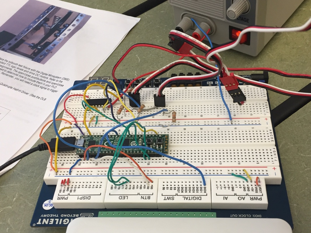
|
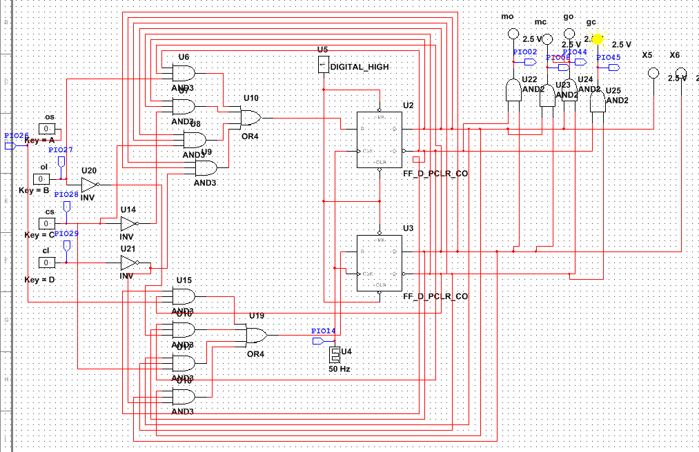
Working simulation
|
PLD Document
Conclusion
Dear Ms. Z,
me and my teammates designed a toll booth, by using many materials. We simulated it on the breadboard and on PLD mode. once we got it working it started to move up and down hitting limit switches. In our breadboard design we used many wires and 3 resistors. we set up the inputs and outputs on PLD mode and on the board and connected the wires to the board and it will would (toll booth). what I would do differently next time is, I would make sure all of the wires are in the correct space so I will not have any or as much mistakes as we had this project, our problem was the wires being connected to the wrong things on the bread board. I found out that it is very hard to figure out the mistakes once you already have the finished project of you have finished it and ready to test the toll booth. I learned that reading schematics is difficult at first when you start, but at the end you will finally understand it because it contains a lot of logic and Boolean algebra simplification which our teacher gave us. The question that I have is on the state graphs, why do they put X variable instead of 0?
sincerely, brynae
