Deli Counter Display!
Project OverView
I had to design a counter that goes from 0 to 80. The design had a reset button and also a pause button which stops at 80. it was not that hard because i could look back at the designs i built in the other activities and relate to the project deli counter display.
Multisim circuit

PLD Circuit
Bill Of Materials
-Paper and Pencil (sketches)
-Circuit Design Software (MultiSim)
-Integrated Circuits
>74LS193
>74LS48
>Common Cathode Seven-Seg Displays
>Wires
>Breadboard
Whats the difference?
Pld mode is abbreviated for programmable logic device. it is the integration between simulation and hardware implementation. You can assign pins after you finished your assignment & transfer it into the board to make it run. The connectors that are in PLD mode can be assigned to certain things like for instance that clock, or the different switches.Design mode, it runs on the computer, you build it and it runs by itsself.
Final Conclusions
The difference between the MSI (Medium scale integration) curcuit and the SSI(small scale integration) circuit is that a small scale is an integration type for digital circuits that contain transistors numbering in the tens providing a few logic gates per chip. The medium, makes things really easy because it has flip flop counters in it. The limitation between my design was that it only could go up to 80 it couldnt go uo any higher if it wanted to. The meaning of ripple effect is the pause that it has between different flip flops when it is changing to a different number also.
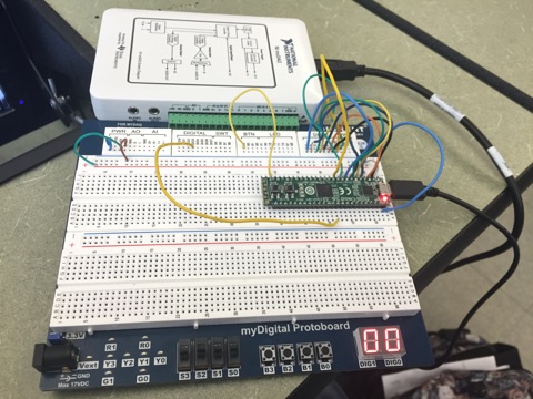
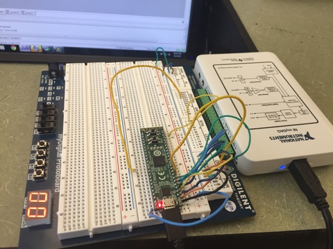
When i pressed the pushbutton which on my design was B3 . Next,signal travels through the 93 chip and it counts.Pin 14 is connected to the clock and Pin 48 is connected to the switch that resets the counter. The pin 26 , 27 ,28, 29, 30,, 31, 32 are connected to A B C D E F G to Make them light up (the probes). i also have connected ground and power to make the board power .
My Teacher stated that all of our designs were different, they were different because each of us used different logic gates to make the circuit reset and also power.
